![]()
![]()
RF Filters
DC Pass/13.56 MHz RF Blocking Filters
![]()
![]()
Sales brochure AC 200, Rev. D 02/18
|
|
Protects DC Power Supplies and Control Systems from Damage & Interference |
|
|
Filters RF from DC Components |
|
|
Low Frequency DC (<1 MHz) Passes Through Without Interference |
|
|
3 watts to 4 KW from 1 to 13.56 MHz |
|
|
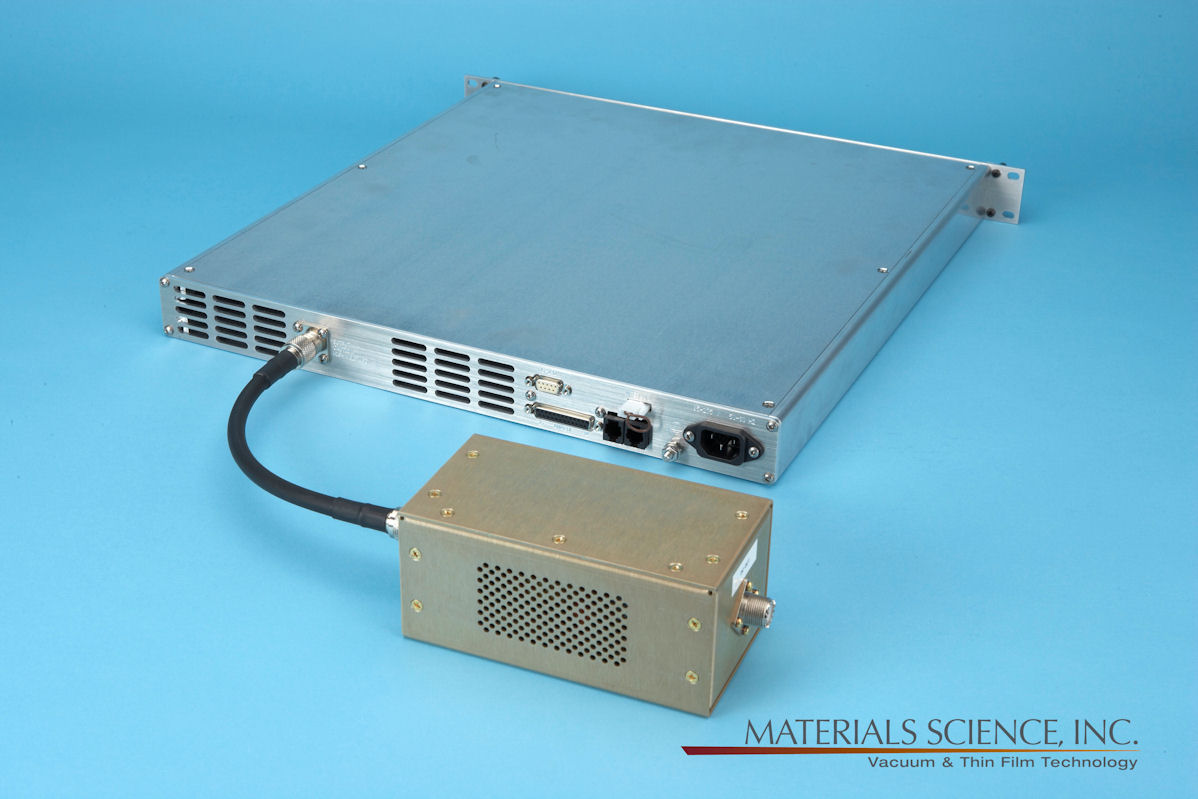
Connects at Output of DC Power Supply |
|
|
CE, CSA & UL Compliant |
| Description
|
Specifications
|
Part Number |
00002374 |
|
Frequencies Attenuated |
1 to 13.56 MHz |
|
Power Rating |
100 to 4000 watts RF (4A @ 1000V) |
|
Input Connector |
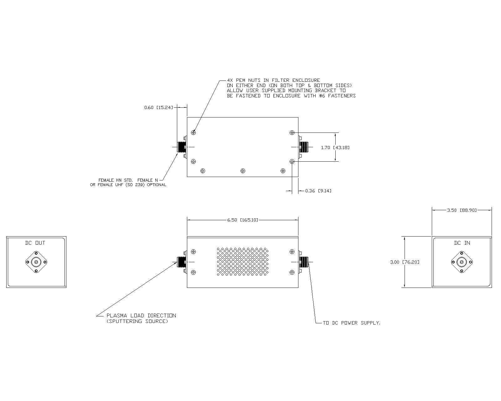
Female HN standard (Female UHF (SO 239) or N optional) |
|
Output Connector |
Female HN standard (Female UHF (SO 239) or N optional) |
|
Size (L x W x H) |
6.50” x 3.50” x 3.00” (165.10 mm x 88.90 mm x 76.20 mm) |
|
Weight |
1.9 pounds (861 grams) |
Interface