Download Technology Note TN 000 100 02/03 Download Technology Note TN 000 100 02/03  
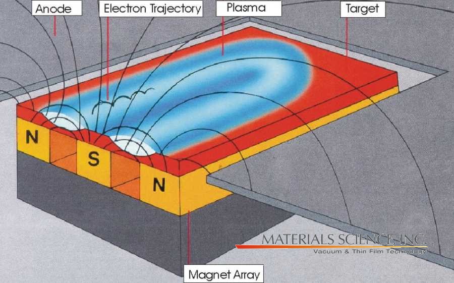
General Principle of Operation The above illustration describes a generic manifestation of a magnetron sputtering source. DC, pulsed DC, AC and RF power supplies may be used, depending upon target material, if reactive sputtering is desired and other factors. A permanent magnet structure is located behind a target serving as a deposition source. Plasma confinement on the target surface is achieved by locating a permanent magnet structure behind the target surface. The resulting magnetic field forms a closed-loop annular path acting as an electron trap that reshapes the trajectories of the secondary electrons ejected from target into a cycloidal path, greatly increasing the probability of ionization of the sputtering gas within the confinement zone. Inert gases, specfically argon, are usually employed as the sputtering gas because they tend not to react with the target material or combine with any process gases and because they produce higher sputtering and deposition rates due to their high molecular weight. Positively charged argon ions from the plasma are accelerated toward the negatively biased target (cathode), resulting in material being sputtered from the target surface. Influence of the Magnet Design There is much discussion regarding advantages and disadvantages of "unbalanced" magnetrons. An "unbalanced" magnetron is simply a design where the magnetic flux from one pole is greatly unequal to the other. The magnetic field does not directly influence ion motion, but ion flux follows that of electrons due to electrostatic attraction. Unbalanced magnetrons increase ion and electron bombardment of the growing film, at the significant expense of target utilization and insulating film growth on the target surface during reactive sputter deposition. High target utilization designs are attempts at arriving at highly balanced magnetrons that confine nearly all the electrons and ions adjacent to the target surface and spread the plasma volume over as wide an area across the target surface as possible. These designs minimize bombardment of the growing film, increase target utilization by as much as 30-40 wt% and minimize the formation of insulating films that result in arcing. The use of an ion beam source or combined ion beam-magnetron sputtering source allows the benefits of high target utilization, minimized insulating film growth on the target surface and simultaneous, independent control of bombardment of the growing film. Target Utilization and Sputtering Rates When designing to optimize target utilization, the most important region of the magnetic field is generally located 0.5-1 inch above the target surface. The following examples are provided to explain the influence of the magnetic field on target utilization and rate. Unbalanced Design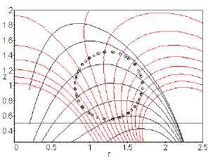 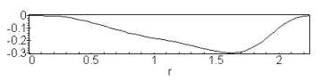
Resulting Erosion Profile for 0.5" Thick Target
from Unbalanced Magnetron Discussion The graphs show the magnetic field lines for unbalanced (above) and balanced (below) magnet arrays for 6 inch diameter targets, the path of the ions, the target surface and the nominal location of the region of greatest plasma intensity. The path of the ions indicates what erosion profile will result on the target. The region and depth of erosion depends on the strength of the magnetic field and how parallel it is to the target surface at 0.5-1 inches above the target, where the bombarding ions originate. Also, the depth depends upon the angle at which ions hit the target. Note that this angle is 90° at r = 1.65 inches (for the unbalanced design) and r = 1.25 (balanced design) and this is the depeste point on the actual targets. A graph of cos3 (q ) is remarkably close to the actual erosion (q is the angle that the incident ion makes with the normal at the target surface). Cos(q) = Br/sqrt(Br^2+Bz^2). High Target Utilization ("Balanced") Design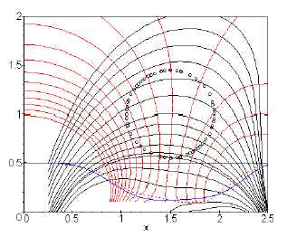 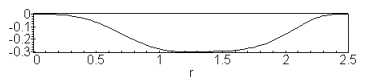
Resulting Erosion Profile for 0.5" Thick Target
from Balanced Magnetron 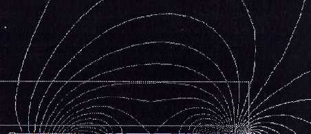
Mathematical Model (above) and FEA
Magnetic Field Lines Model (at right)
indicating the influence of parallel field
lines in the region 0.5 - 1 inch above
the target surface on target utilization Restated - although it’s not strictly true, it fair to say for the purposes of this summary that the region of material removal generally mirrors the shape of the magnetic field lines 0.5 - 1 inch above the target surface. Use of targets which are significantly thicker or thinner results in worse target utilization, narrower operating pressure range, distribution profiles which vary significantly from predicted results and degraded performance. Why? The electrons which create the plasma discharge are accelerated toward the target at a 90° angle relative to the magnetic field lines. Therefore, when the field lines are “flat” across the target surface it is uniformly eroded. The steeper the angle is at the target surface, the more “pinched” the erosion groove will be. Using targets which are too thick creates this condition. The area of target material removal does not increase as the target erodes. Once the erosion profile has been established on the target surface, it will remain constant throughout the life of the target. Another significant drawback to using targets which are too thick is that this promotes areas of material redeposition and insulating film growth (since very weak or no plasma discharge is present where the target is not being eroded) to prevent this situation from occurring. |