|


| |
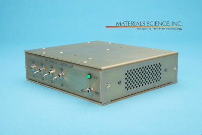
DC/RF
Power Supply Switches
 Sales Brochure AC 400, Rev.A 02/18
Click
here for
installation control drawings
 |
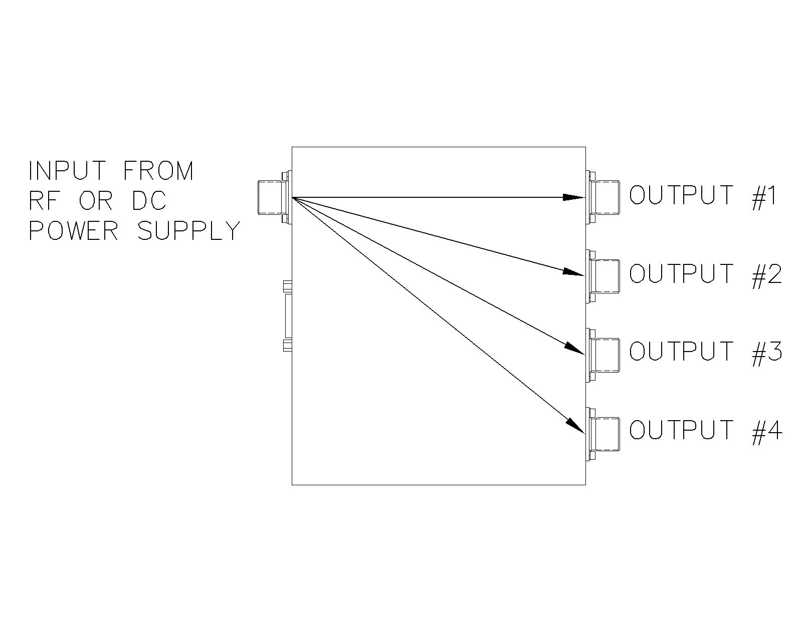
Low cost method to
sequentially run multiple sputtering
sources using a single DC or RF power supply |
|
|
2, 3 or 4 output models |
|
|
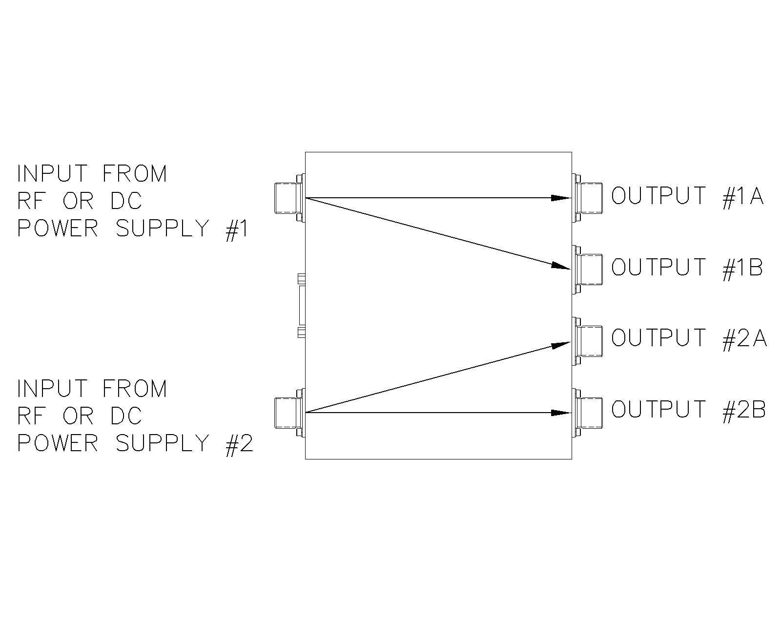
2 power supply input
models allow two power supplies (any combination
of RF and DC) to be connected to a single switch. Each power supply
can be switched between 1 of 2 outputs per power supply. |
| Description These
modules provide an easy way to remotely switch the output of one or two
power systems between two sputtering sources per power supply. This
provides a cost-effective approach in many R&D environments. They
can replace the need for multiple separate power supplies at
considerable cost savings.
In the case of multiple sputtering sources using RF
power, it is best that an individual impedance matching network be
provided for each source, with the power switch located between the RF
power generator and the impedance matching network. This ensures the
individual load represented by each sputtering source can be optimized
for different target materials and varied states of erosion. If
the switch is located after the output of a single impedance matching
network, it is likely that the network will have to be adjusted to
compensate for significantly different loads (ie - metal target on one
source and a dielectric target on the second source).
High quality vacuum relays are used in the switches
instead of open frame relays. Vacuum relays are preferred because
they are more robust and provide reliable long-term operation.
Control
The user must provide the necessary 24 VDC (<
1 amp) signals needed to operate the relays from a PLC or computer
control system. An optional 1/2 rack remote controller is
available. The controller comes with a 10' control cable. |
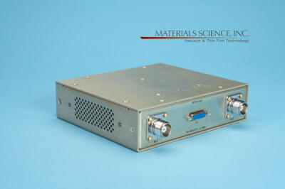
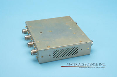
Two Input Switch
Optional Remote Controller
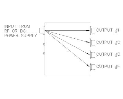
One Power Supply Switched Between Up to 4 Outputs
One RF and One DC Power Supply (or two of each type) Connected to
Switch Allows Two Outputs per Power Supply.
Both Power Supplies Can be Run Simultaneously.

Ordering Information
| Part Number |
Description |
|
00002391-1 |
RF/DC Switch - 1 input, 2 outputs. 3 watts to
5kW. All connectors are
female HN. |
|
00002391-2 |
RF/DC Switch - 1 input, 2 outputs. 3 watts to
5kW*. All connectors are
female UHF (SO 239) |
|
00002391-3 |
RF/DC Switch - 1 input, 2 outputs. 3 watts to
5kW*. All connectors are
female N |
|
00002383-1 |
RF/DC Switch - 1 input, 3 outputs. 3 watts to
5kW. All connectors are
female HN. |
|
00002383-2 |
RF/DC Switch - 1 input, 3 outputs. 3 watts to
5kW*. All connectors are
female UHF (SO 239) |
|
00002383-3 |
RF/DC Switch - 1 input, 3 outputs. 3 watts to
5kW*. Female HN input, Female
N output |
|
00002392-1 |
RF/DC Switch - 1 input, 4 outputs. 3 watts to
5kW. All connectors are
female HN. |
|
00002392-2 |
RF/DC Switch - 1 input, 4 outputs. 3 watts to
5kW*. All connectors are
female UHF (SO 239) |
|
00002392-3 |
RF/DC Switch - 1 input, 4 outputs. 3 watts to
5kW*. All connectors are
female N. |
|
00002392-4 |
RF/DC Switch - 1 input, 4 outputs. 3 watts to
5kW*. Female HN input, Female
N output |
|
00002384-1 |
RF/DC Switch - 2 inputs, 2 outputs per
input. 3 watts to 5kW. All connectors are
female HN. |
|
00002384-2 |
RF/DC Switch - 2 inputs, 2 outputs per
input. 3 watts to 5kW. All connectors are
female UHF (SO 239) |
| 00002555 |
Remote Controller in 19" 1/2 rack, 1U high
enclosure |
Note: Other connector set combinations are possible.
Contact factory.
Specifications
|
Power Rating |
3
to 5000 watts |
|
Input Connector(s) |
Female HN standard - Other connector types limit maximum power
rating |
|
Output Connectors |
Female HN standard - Other connector types limit maximum power
rating |
|
Size (L x W x H) |
6.50” x 7.50” x 2.00” (165.10 mm x 190.50 mm x 50.80 mm) |
|
Weight |
3 pounds (1.36 kg) |
Technical Considerations
| Operation Turn off the
power supply before changing the power output selection. These
switching modules are not interlocked and therefore the user will need
to ensure that the relays are not "hot-switched" as extreme damage to
the relays will occur.
This type of damage is not covered under warranty. |
| Output Power Cable Length
We suggest that you use a maximum RG-393 cable length of
36" [915mm] when using RF power supplies. This length will limit
the amount of lost RF power (as heat) and maximize the power transfer to
the sputtering source.
DC magnetron power supplies should use cable lengths
of 8-10' [2.5 - 3 meters]. |
| Coaxial Cable Types
RF Power: RG-393 should be used.
Do not used RG-400 unless the power level is below 100 watts.
DC Power: RG-8/U should be used. |
| Matching of Different RF Sputtering Cathode
Impedance Each user will require a somewhat
different RF matching configuration based upon cable lengths, target
materials and overall process conditions. A typical single
sputtering source/impedance matching network combination is optimized to
match just the connected source. If the user changes target
materials (i.e. sputtering a metal and then changing to a dielectric),
then the matching network may require adjustment of the series inductor
(changing the tap setting) or in some cases the addition of fixed shunt
capacitance. Always refer to the matching network instruction
manual for specific information relating to setting up the match. |
|
* Limits on Maximum Power Rating Due to Connector Types
The vacuum relays used in the switch are conservatively rated for 5kW
service. However, of the three most common connectors used (HN, UHF and
N), only HN connectors have a sufficiently high voltage rating (5000V
Peak) to guarantee the 5kW rating. Depending upon where switches with
UHF (500V Peak) or N (1500V Peak) connectors are located (at the output
side of the matching network or in-between the power generator and the
matching network) in RF systems or simply the connector type when used
just with DC power supplies, the maximum power rating will be lower.
Consult the factory for your specific situation. |
|