


| |  GEN II GEN II
Magnetron Sputtering Source Performance Characteristics Be fully informed when making process & engineering decisions  Printable PDF Version of This Page Printable PDF Version of This Page
SUMMARY OF BENEFITS
The broad plasma discharge that produces good target utilization also prevents significant redeposition of material in non-active areas and greatly reduces the chances of highly stressed redeposited material breaking and causing film defects. Gases that evolve during arcing change the film composition and contribute to an unstable process environment. Multilayer stacks are very sensitive to this problem. The broad plasma discharge minimizes the possibility of oxide formation on the target which subsequently sputter through and arc. The stability of a process throughout the life of a target is critical, especially for reactively deposited films. Metal oxides and nitrides are particularly sensitive to arcing and particulate generation and are difficult to deposit at high rates. High rates of uniform, turbulent water flow result in efficient target cooling and heat removal. No localized hot spots promote oxide formation and whisker growth. Consequently there are fewer and lower intensity arcs resulting from this. Argon gas through the cathode body results in clean target surfaces, localized high pressure on the target surface, a more stable plasma and higher rates. What Influences Target Utilization? Here's the truth about target utilization - there are no absolutes for the source from any manufacturer and the same source will produce sometimes significantly different results depending upon a number of factors including the system the source is installed in, target thickness, background pressure, power level, composition & quality of target material, sputtering gas composition and type of power supply used. Some of the more common practical factors encountered in daily use are briefly discussed below. A detailed discussion on magnetic design & target utilization can be found by clicking here. |
inter-relationSHIP of Target Utilization, Distribution uniformity & insulating film growth  
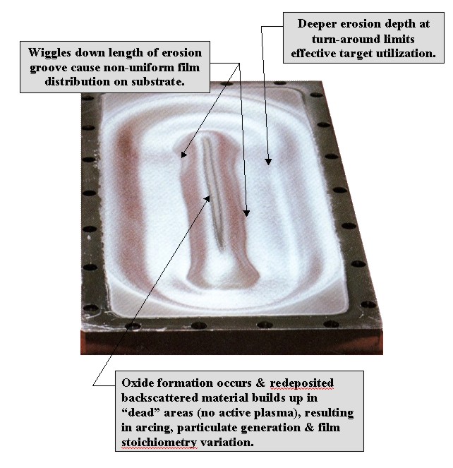
Useful Target Life vs. Wt% Target Utilization Target utilization as specified in our sales literature is defined as the amount of material sputtered from the target during use (wt%). This is a long-time industry practice. If every manufacturer of sputtering sources used the same baseline methodology to determine target utilization, then this might be a useful way to compare the performance of one source to another. Sorting the marketing claims from reality requires experience and a practiced, skeptical eye. A better way to think about how long a target will last and yield desirable results before it needs to be replaced compared to how much of it can actually be sputtered is to define what constitutes useful target life in KWHrs. This can be programmed into control systems as a quality control variable and takes the times that the source has been run with the same target installed at different power levels into account. Cracking of doped Si targets with oxygen present as a reactive gas is a classic example where actual target utilization is much less important than process results. Stresses in the material almost immediately create cracking during thermal and pressure excursions.. When plasma discharges begin to form within the cracks they begin to produce much higher and lower rates from different areas within the erosion groove, mandating target replacement. In this case, the use of thinner targets bonded to a backing plate thick enough to bring the surface of a new target to the optimal location for the best target utilization produces the best useful target life, but not necessarily the best wt% target utilization we could claim with our salesman's hat on. Clean target surfaces and reduced arcing due to the broad plasma discharge that produces good target utilization are in this case much more important than the ability to consume a high percentage of a thicker, inexpensive material. Pragmatically speaking, target utilization of nominal 35wt% for 6" diameter x 0.25" thick doped Si targets bonded to 0.25" thick backing plates is real life, not the nominal 40wt% utilization for a 0.50" thick target that could be claimed. Good Target Utilization Doesn't Necessarily Translate Into Good Thin Film Uniformity or Film Quality on Your Parts There are multiple ways to achieve decent to good target material utilization on linear sources. Some are more susceptible to "wiggles" down the target length than others. Round and linear sources can exhibit significant erosion profile changes as the target erodes. The magnet arrays of SunSource GEN II™ sources are not sensitive to the kinds of non-uniform erosion patterns ("wiggles" and significant changes of the erosion groove depth) illustrated above that are very common in the sources provided by many of our competitors. Some sources will only provide good target utilization at relatively high pressures (4-5 mTorr), resulting in argon and background gas inclusions in the growing film, bad adhesion and poor film density. This is due to poor electron confinement efficiency near the target surface - an artifact of the magnet array design. The ability to operate efficiently in the 10-4 torr region and achieve good utilization s a unique characteristic of SunSource GEN II™ sources. Good target utilization is irrelevant when you have terrible process conditions. The Target Material Affects Utilization In general, the higher the sputter yield of elemental targets, the better the wt% target utilization and erosion profile that can be expected. Compounds & Alloys Sputter Preferentially Compound and alloy targets can potentially act very differently due to preferential sputtering of the various elements in the target. There is no good way to predict the outcome of using such a target short of actual experience. |
Power Level Materials Science, Inc. Competing
3.5" wide x 15" long target 5" Wide x 15" long target
@ 2kW Total Input Power @ 2kW Total Input Power 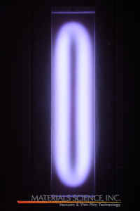 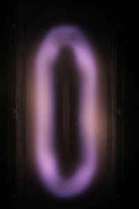
It's important to understand the concept of "plasma volume." A reading of the magnetic design & target utilization tutorial will familiarize you with this concept. Simply put, the area of target erosion is determined by the amount of power applied to the region of efficient electron confinement over the target surface. Within limits, the plasma volume will expand and contract over the target surface depending upon the power density. Again - oversimplifying the example - the region below the plasma volume on the target surface is the area of active target erosion. A visual inspection of the visible optical emission and brightness over the target will correspond to target erosion. Running any source at very low power densities will result in diminished target utilization, independent of the magnet design. Using a source with a 90mm or 3.5" wide target instead of one using 5" or 6" wide target, assuming the same total power input can lower target costs, improve effective utilization and overall performance. |
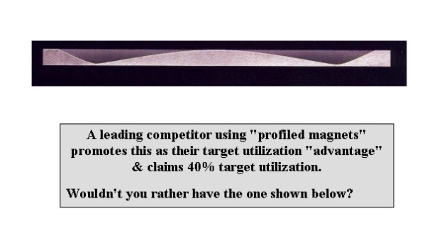
Beware of Target Utilization Sales Brochure "Specmanship" Your eyes do not deceive you!! At least in this case. Ask to see real examples of eroded targets, or better yet, the real thing. It's one thing to say "me too" and quite another to withstand a side-by-side comparison. Understand the conditions under which the results were obtained. Consider why some of our competitors NEVER show photographs or examples of eroded targets while making claims of equivalent performance. Others make claims nearly twice ours and do show photographs, but they look just the same as the results we post. Think critically and don't be misled. There are multiple ways to nearly the same result, but no miracles in physics (although during exams or orals we have all wished differently!). The use of rare earth magnets does NOT automatically provide better target utilization and in fact, stronger magnets are less stable and more sensitive to heat and degaussing. Their use provides designers with the ability to execute designs with properties that could not otherwise be achieved because rare earth magnets allow small mass magnets with field outputs equivalent to much larger mass magnets to be produced. Absent a well-balanced design, the high voltages and strong stray magnetic fields create source self-sputtering, arcing, interaction with ground planes and other system devices, substrate heating and poor target utilization. 
|
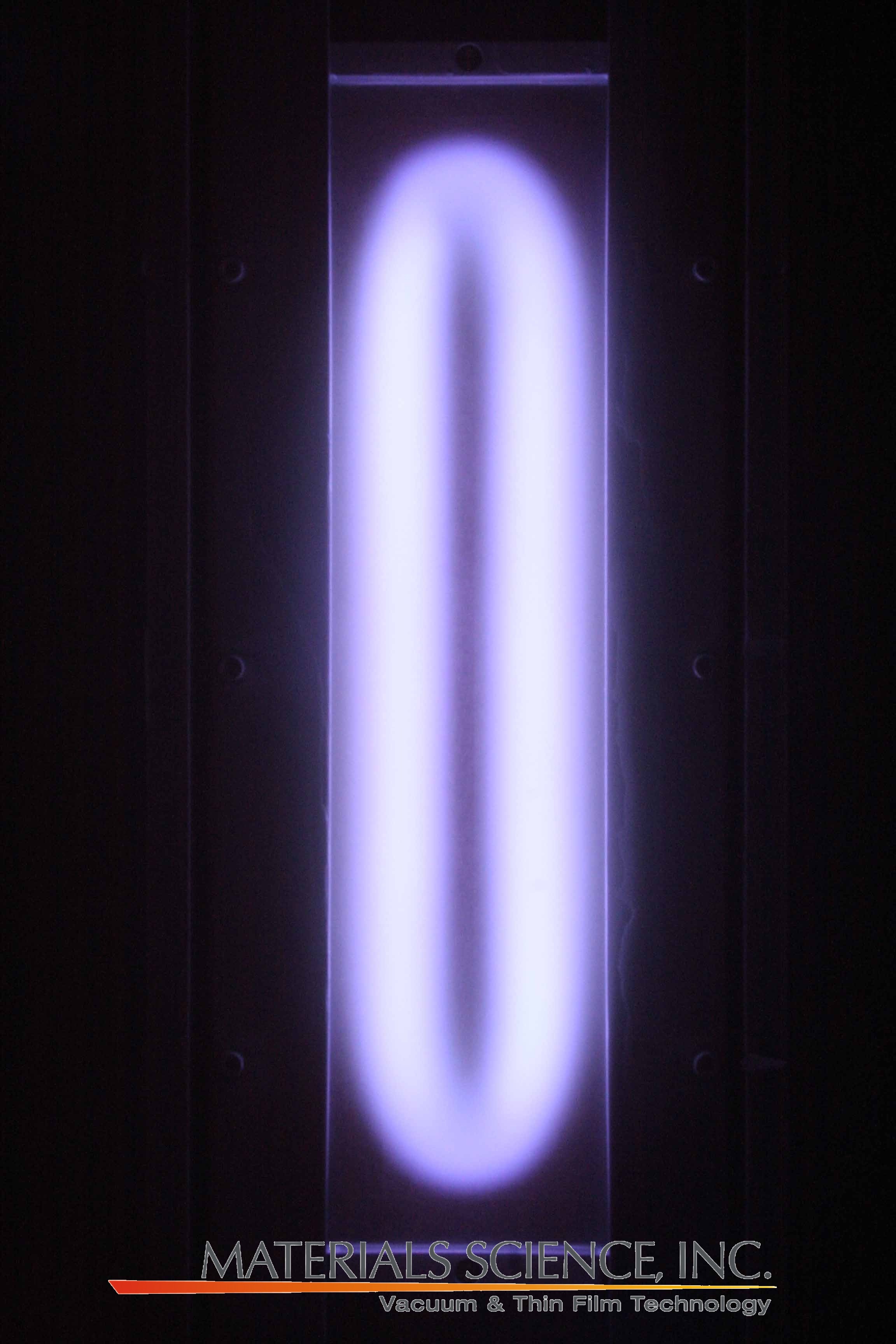
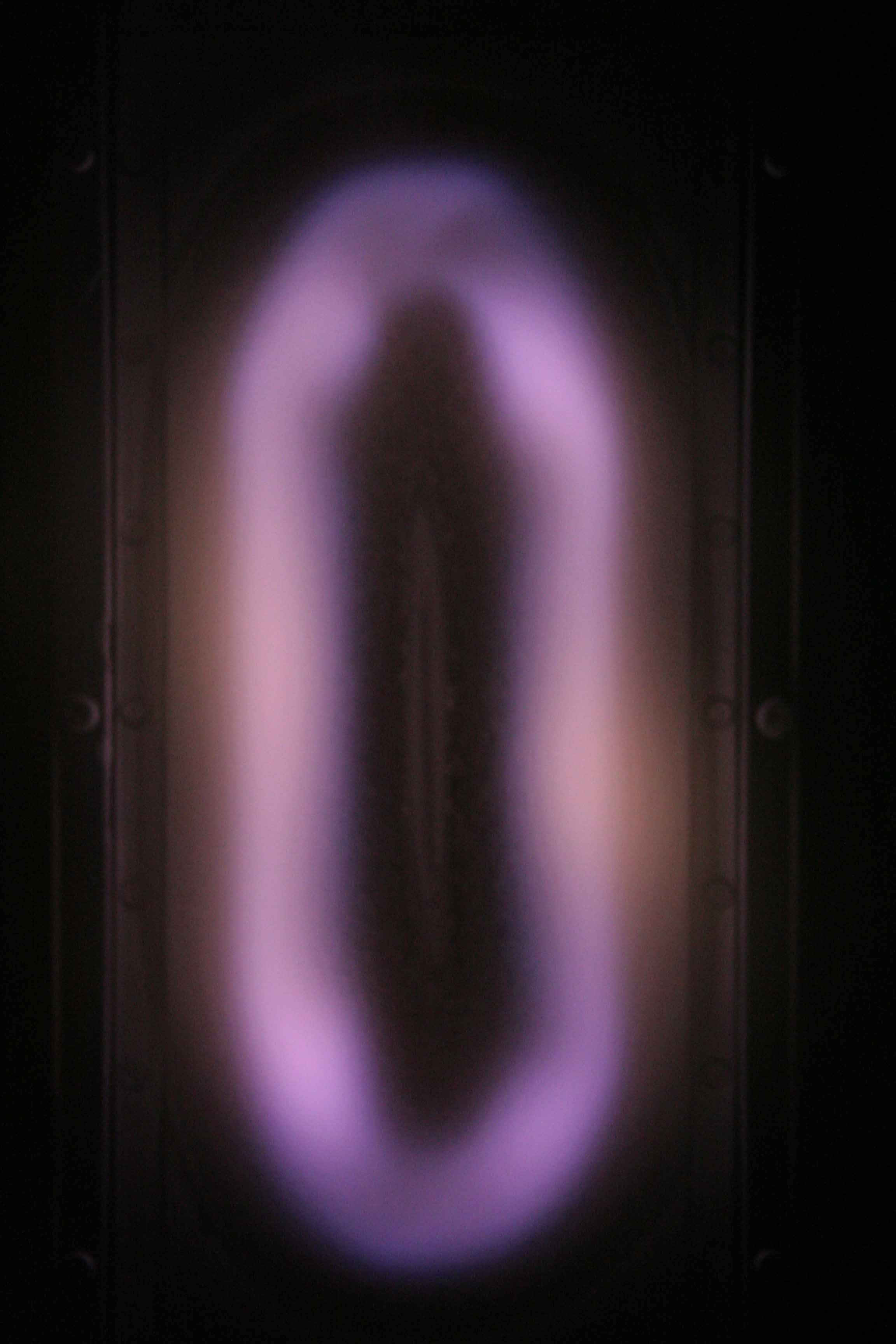
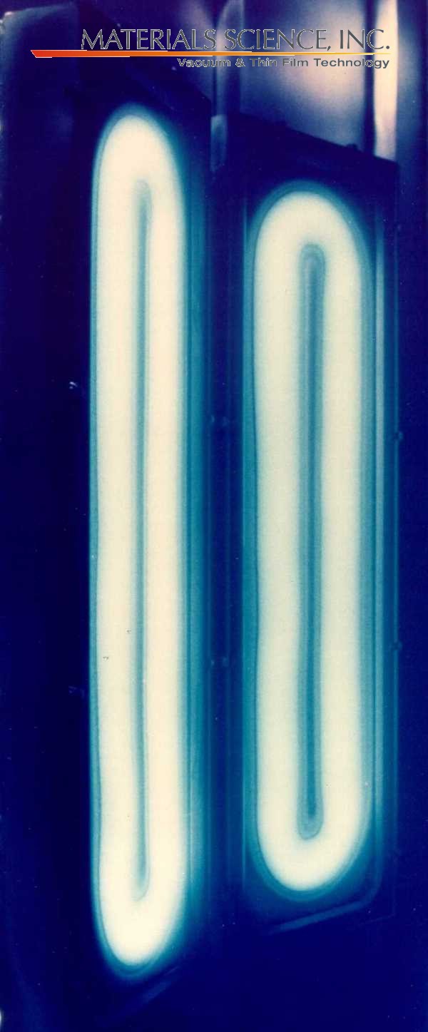
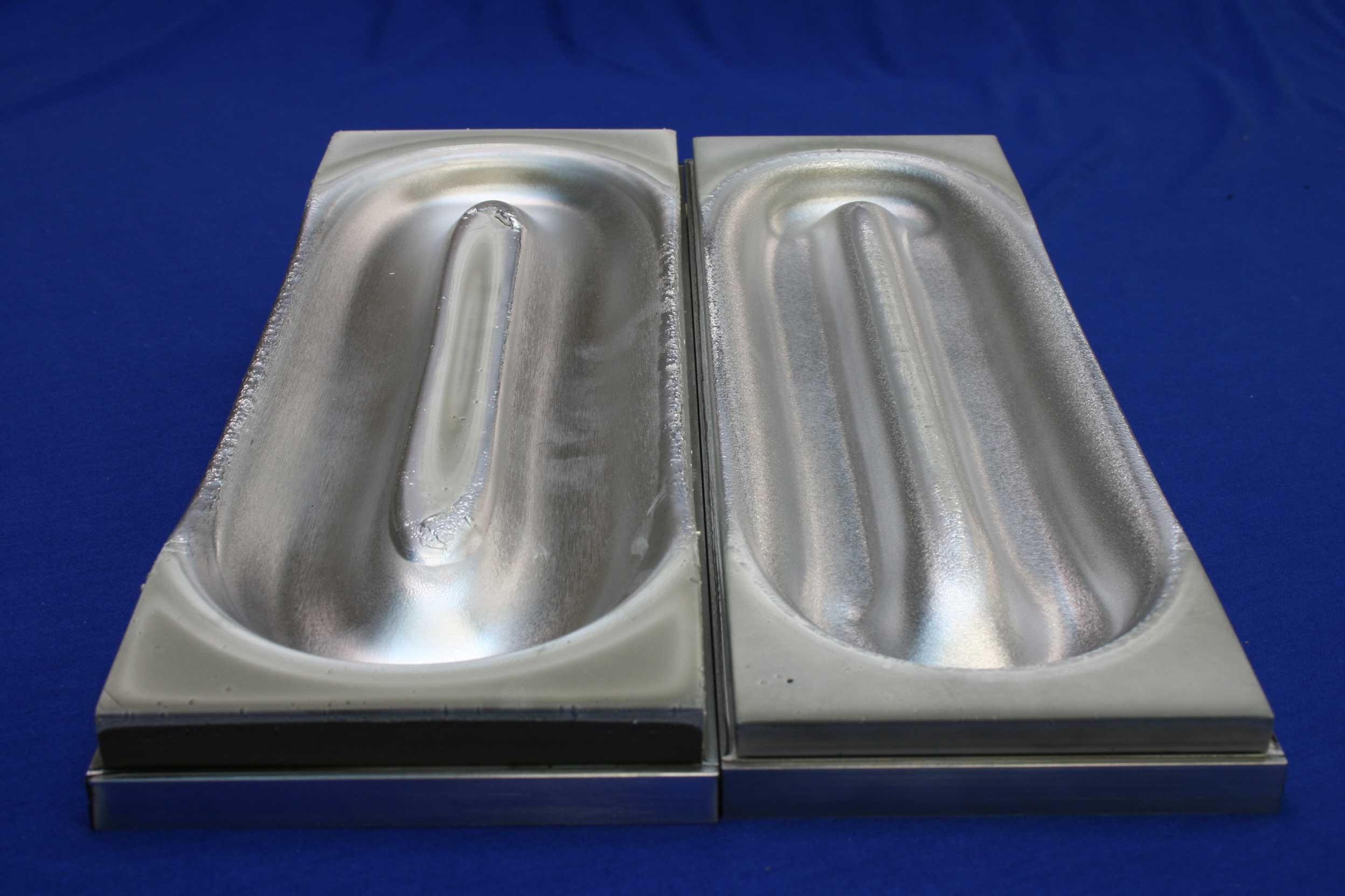
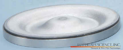
Benefits of Gas Injection Through the Cathode Body & Broad Active Plasma Discharge Across Target Surface 
This AC cathode pair using 5" wide targets is used to deposit Al2O3 reactively from aluminum targets. The broad active plasma discharge spread across nearly the entire target surface reduces insulating film growth, arcing & thus changes in film stochiometry during film growth. This is also true run-to-run throughout the target lifetime. Note the bright optical emission region of the plasma discharge. The center "dead" area is small, even in the presence of high background levels of oxygen, indicating minimal redeposited material and insulating film growth. The broad plasma discharge creates an active plasma region that keeps the target surface "clean" and non-poisoned (Insulating film growth), even in the areas of the target that are not being actively sputtered. Gas injection (Argon and other gas mixtures such as Ar/O2) through the cathode body creates a localized area of relatively high pressure, tending to push away backscattered target material. Introducing reactive oxygen through the body also can allow some reactive films to be deposited without the use of separate ion and plasma sources because the plasma can potentially activate the oxygen sufficiently. This feature also eliminates the use of gas distribution manifolds (much lower gas consumption since the entire chamber does not have to be brought to the most efficient sputtering pressure), potentially allows the use of smaller, less expensive pumps (lower gas throughput requirements), produces uniform pressure across the target surface even in systems with significant pressure gradients across the chamber and in combination with the highly efficient electron confinement of the magnet array design allows stable operation at low 10-4 torr pressures and low rates - especially important in applications with very thin multi-pair layers and stacks. |
Multiple Gas Circuits Provide Even More Control of Pressure Across the Target Surface in Long Sources Not only do SunSource™ & SunSource GEN II™ linear sources have gas distributors within the cathode body, but they allow the possibility of multiple, gas distribution segments that allow the source to be "tuned" to compensate for pressure variations across the substrate that induce film non-uniformity. |
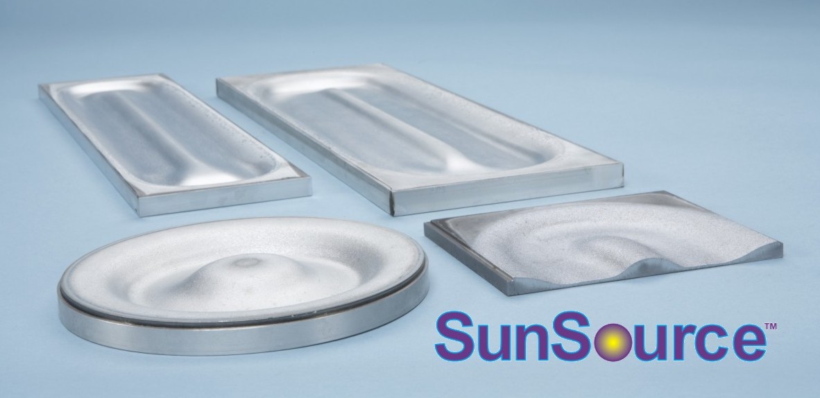
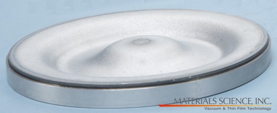
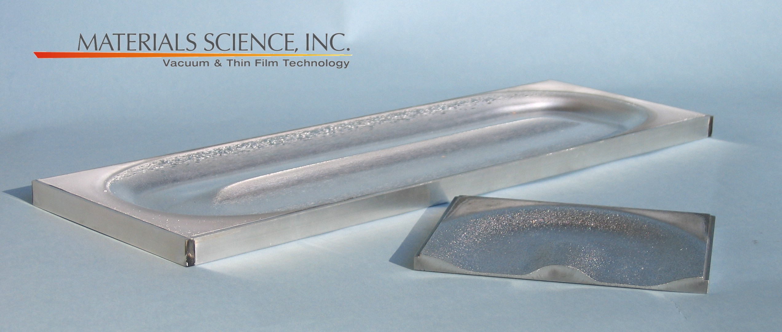
| Target Thickness Changes the Erosion Pattern & Effective Utilization 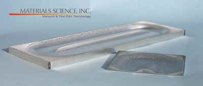
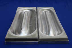 All of the targets shown above and at the right (ranging between 0.25" to 1.00" thick) were eroded on the same source with the same highly balanced magnet array. Note that the amount of material redeposited in the center region increases significantly when using very thick targets. Because the region of efficient electron confinement produced by the magnetic field becomes less balanced for very thick targets two things occur. The first is that effective target wt% utilization drops because the broad erosion area narrows. Secondly, because the active plasma discharge is not completely confined to the target surface, the sides of the target down the length begin to sputter -making the target clamping rings consumable items and sources of film contamination. All of the targets shown above and at the right (ranging between 0.25" to 1.00" thick) were eroded on the same source with the same highly balanced magnet array. Note that the amount of material redeposited in the center region increases significantly when using very thick targets. Because the region of efficient electron confinement produced by the magnetic field becomes less balanced for very thick targets two things occur. The first is that effective target wt% utilization drops because the broad erosion area narrows. Secondly, because the active plasma discharge is not completely confined to the target surface, the sides of the target down the length begin to sputter -making the target clamping rings consumable items and sources of film contamination.
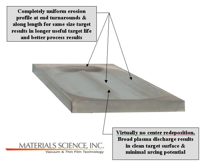
As the detailed discussion on magnetic design & target utilization explains, the erosion profile generally mirrors the shape of the magnetic field lines above the target surface. Target utilization and the profile of the erosion area will not change as the target erodes. Once the basic profile is established on a new target, it will remain constant. Use of targets which are significantly thicker or thinner than the source has been designed for results in worse target utilization, narrower operating pressure range, distribution profiles which vary significantly from predicted results and degraded performance. SunSource GEN II™ sputtering sources have been designed to provide the longest useful target lifetime and the best process results during that time. |
| Sputtering Rate & Distribution Uniformity Distribution uniformity and rate will remain consistent throughout the life of the target because the erosion profile does not fundamentally change as the target erodes, provided that targets with the recommended thickness are installed. A far smaller percentage of low angle material sputtered from the erosion region hits the side wall of the groove compared to narrower grooves with steeper side walls, minimizing distribution variation. The voltage change when a target is fully eroded is on the order of 50% that compared to other sources due to the wide, stable erosion profile (actual value is material sensitive). A practical benefit of this is that it will not be necessary to reset the power supply taps when it becomes current limited during the middle of the target life and that a constant power level can always be maintained through regulation of the power supply (constant power mode). The magnet design of SunSource GEN II™ sources is fairly insensitive to differences in the strength of individual magnets that can develop, especially when the source is run at high power levels over an extended time period. The variation in the strength of adjacent magnets that can cause the "wiggles" along the length of the erosion profile illustrated at the top of the page and uneven distribution from the source does not occur. The plasma volume limits the amount of power that can be applied. About 25-30% more power can be applied to SunSource GEN II™ sources as a result of the broad plasma discharge. Consequently, rates are similarly higher. In most cases, the limit to the amount of power that can be applied is the target material itself and how it is mounted in the source, not an intrinsic limit in the source itself. |
| Cooling The exit water flow through the cathode body is the same as the inlet flow. There are no internal water flow restrictions or backpressure. The clear ID of the water fittings matches that of the recommended inlet and exit water lines. Uniform, turbulent flow between the target assembly and magnet module ensure that cooling is most effectively located in the region of highest temperature. The result is higher achievable power levels and uniform target cooling mitigating against hot spots & whisker growth. Effective cooling of the magnet module is assured by the circuit design within the cathode assembly. This prevents premature degaussing of individual magnets within the module. Weak magnets require increasingly higher operating voltages and higher process pressures. Target utilization degrades and premature burn-through of the target at the ends is likely. Rates will drop and distribution from the source will become skewed. |
|